Evoqua United States - Canada - EN

Is Hydrogen Safe?

Evoqua answers frequently asked questions about Hydrogen Safety within industrial applications where electrochlorination is utilized

hydrogen-safety-article-card-img

Article Summary:

• Hydrogen production is common across all electrochlorination systems

• Best practices and third party review process

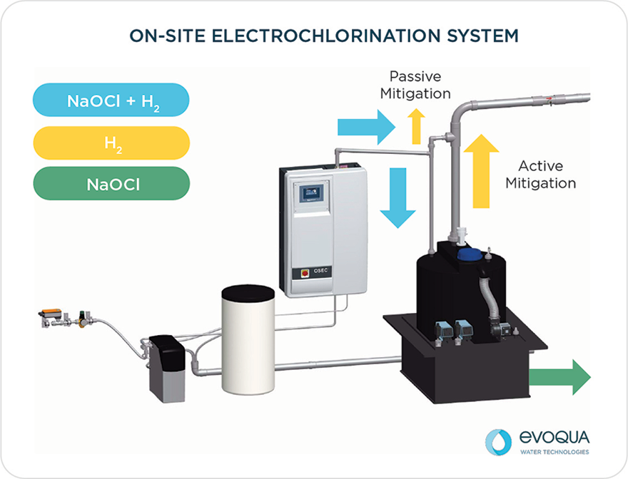
• Evoqua’s OSEC® system position and rationale for design

• Summary of Evoqua’s position and commitment to safety


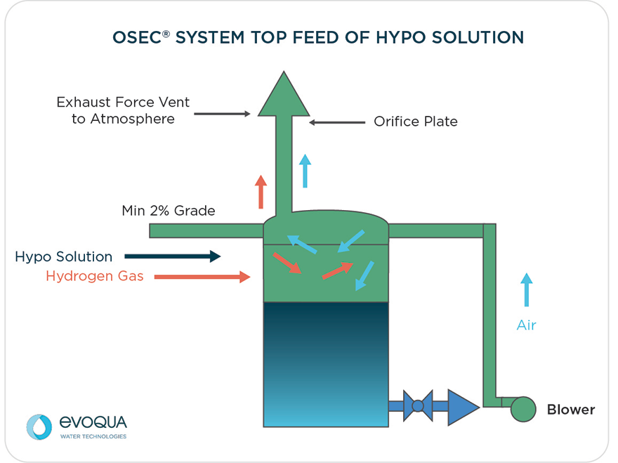
Hydrogen Production With On-Site Sodium Hypochlorite Generation


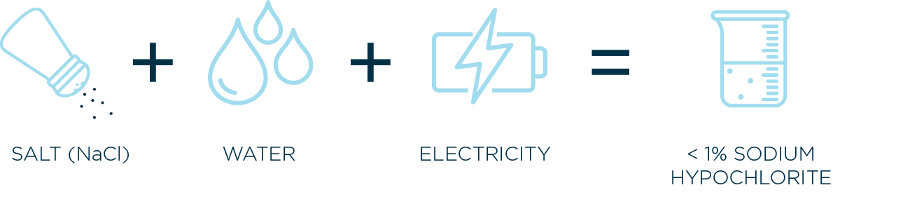
On-site electrochlorination, often referred to as OSHG, provides valuable security of supply by generating a sodium hypochlorite solution on-site, on-demand for the treatment of water, by only using salt, water and electricity.


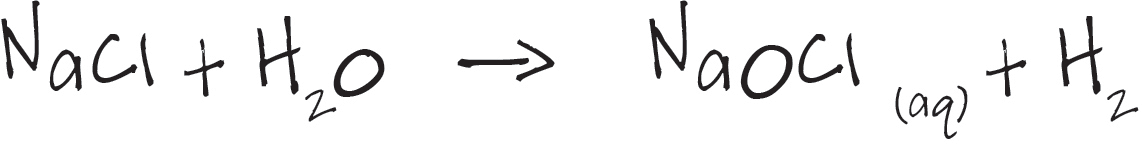
What normally isn’t talked about when it comes to electrochlorination is that hydrogen gas is generated during the electrolysis process at the surface of the cathode plates.

osec-equation-a

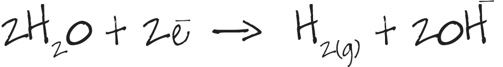
At the cathode, because of its abundance and electrochemical potential, water is the primary recipient of electrons donated by the cathode plate when it is energized. By taking electrons, water is reduced and electrolyzed (electrochemically separated) into hydrogen gas (H2) and hydroxyl ions (OH-).

Since hydrogen gas has a very low solubility in water (<1.6 mg/L at 25°C), it forms small bubbles on the surface of the cathode, and evolves from the solution. This implies that hydrogen gas will accumulate at the top of the cell if not removed. The overall cathode reaction is shown in equation 4.1:

osec-equation-b

Two electrons are consumed and two water molecules are consumed to form one molecule of hydrogen gas (H2).

The rate of hydrogen generation depends on the total cathode surface area in the electrolyzer and the total current (energy per unit time) passing through that surface. At typical operating conditions (T=70°F) and assuming 100% current efficiency, which represents the highest hydrogen generation rate possible, the OSEC® B-PLUS electrolyzers produce approximately 0.0063 cfm (cubic feet per min) of H2 per chlorine ppd (pounds per day).

Rule of Thumb
Hydrogen Generation Rate [cfm] = (Cl₂ ppd) *0.0063 Specific Volume = 192 ft³/lb @ 70°F

Hydrogen can form a flammable gas mixture when mixed with air. For hydrogen combustion to occur, two necessary conditions must be met:

  1. The concentration of hydrogen must be between 4% and 75% by volume.
  2. An ignition source (spark or flame) must be present.

Hydrogen is present in the system in three different places: inside the electrolyzer, in the pipe connecting the electrolyzer to the hypochlorite tank, and in the hypochlorite tank. Several measures must be taken at each of these three places to eliminate ignition sources and/or reduce the hydrogen concentration significantly below its Low Flammability Level (4% v/v).

The outlet of an electrolyzer is a two-phase mix of sodium hypochlorite and hydrogen gas. It is important to note that hydrogen exists in three different phases at this point:

  1. Hydrogen in the bulk gas phase.
  2. Hydrogen entrained in the liquid phase as bubbles.
  3. Hydrogen dissolved in the liquid phase.

Hydrogen gas bubbles generated on the surface of the cathodes provide a very large interface area between the liquid and the gas phase. Therefore, equilibrium of hydrogen in the gas phase (H2 bubbles) with the hydrogen in the liquid phase (dissolved H2) is reached quickly. This equilibrium is defined by the solubility of hydrogen in water, which is expressed in terms of its Henry’s constant, H. At 25°C, H = 50.2 L/L or 1228 atm-L/mol. The solubility of hydrogen can be calculated from this value to yield 1.6 mg/L.

The significance of this solubility value is that even after removing the bulk gas phase, hydrogen still exists in the solution as both entrained hydrogen bubbles and dissolved hydrogen. This hydrogen will eventually evolve from the solution at the storage tank. Therefore, all hypochlorite storage tanks must be force-ventilated.


Best Practices


These properties of the electrochlorination process are consistent across all manufacturers of low strength (<1%) brine based on-site solutions. That being said there are many ways to effectively mitigate hydrogen. There are different third-party bodies that help certify or validate these approaches, such as ATEX, TUV, and IBExU to name a few.

Rule of Thumb
Always follow the manufacturer’s recommendations for proper installation, and ensure that installers and operators review and adhere to installation guidelines, regardless of industry approaches from validated third-party entities


The Evoqua Solution to Hydrogen Mitigation


At Evoqua, with our OSEC® units we believe that the following safety measurements should be followed:


  1. All instruments in the electrolyzer must have intrinsic safety barriers.
  2. Electrolyzer liquid level must be monitored. Generation system must shut down if liquid level is low enough to expose electrode plates to a hydrogen atmosphere.
  3. All instruments located at the top of the hypochlorite tank must have intrinsic safety barriers.
  4. The safest place to separate hydrogen gas from the hypochlorite solution is the hypochlorite storage tank, where enough ventilation can be provided to remove not only the bulk hydrogen gas, but also the entrained and dissolved hydrogen over time.
  5. To ensure that all hydrogen makes it to the tank and is properly diluted, the piping connecting the OSEC® system electrolyzer to the hypochlorite tank must:
    1. Maintain a 2% (¼” per ft) upward slope toward the tank.
    2. Avoid any points of potential hydrogen accumulation (downward pipe)
    3. Minimize points of potential leaks (unions, elbows, tees, valves etc.)

Glossary of Terms

General Terms

Intrinsic Safety Barriers

In the electrolyzer, ignition sources are eliminated by using intrinsic safety (IS) barriers for all instruments mounted on the cell. Intrinsic safety barriers are devices that limit current, voltage, and total energy delivered to a sensor or other instrument located in a flammable atmosphere. Intrinsically safe instruments are not capable of releasing sufficient energy in a circuit to ignite a flammable atmosphere.

Liquid Level in Electrolyzer

To avoid exposure of electrodes to a hydrogen gas environment, the liquid level in the cell must always be maintained at a level higher than the electrode plates. If the liquid level were to drop and expose electrodes to the gas atmosphere, electrodes could arc, creating an ignition source.


To reduce the likelihood of accumulation of large volumes of hydrogen gas in electrolyzer cells, OSEC® system electrolyzers remove hydrogen at the point of generation.

Blower Terms

Function

All hydrogen gas produced by the OSEC  system electrolyzer must be diluted down to 1% by volume in air to ensure its safe disposal. At least one blower should be furnished for each hypochlorite storage tank. Two blowers (main and redundant) are an option.  Blown or ventilated air out of the tank is to be expelled into a well-ventilated space (to the outdoors or a well-ventilated room or space).

Control

The appropriate operation of the blower must be monitored at the tank vent pipe to provide positive indication of blower performance. To ensure that the appropriate air flow rate is passing through the hypochlorite tank, an orifice plate is installed at the vent pipe. The orifice plate measures pressure drop through the orifice, which is an indirect measurement of flow rate. The orifice plate is connected to a differential pressure switch, which shuts the system down in the event the flow rate falls below the minimum required to ensure a concentration of 1% of hydrogen in air by volume. In the event of a low-flow alarm, the control panel will automatically switch to the stand-by blower. If the alarm persists, the system will shut down.

Construction

Blowers must be constructed of aluminum or other suitable materials to prevent spark formation.

Sizing

Blowers must be sized to ensure that the air flow rate going into a hypochlorite tank is large enough to reduce the concentration of incoming hydrogen gas to less than 1% v/v. The minimum blower capacity can be calculated with the following expression:

Static Pressure

The capacity of the blower is expressed as flow rate (cfm) at a given static pressure (inches of water column). The static pressure represents the total head that the blower needs to overcome. Since hypochlorite storage tanks are atmospheric tanks (not designed to be pressurized); the static pressure of the system should be minimized (typically < 4” WC ) to avoid tank pressurization. Blowers need to be selected after the individual system and orifice pressure losses are determined. This is dependent upon system layout and vent sizing.

osec-mitigation-graphic-smaller

Flow Orifice

The orifice assembly is installed in the product tank discharge piping to monitor air flow. The vent line into the orifice must be the same diameter as the orifice assembly. It must run straight and for at least 10 pipe diameters prior to the orifice and 5 pipe diameters downstream to ensure proper operation of the orifice. The diameter of the orifice plate should be specified to obtain a 1.5 – 2” WC ΔP at the required air flow rate to maintain the concentration of hydrogen gas to less than 1% v/v. There are two 1/4” ports on the orifice assembly. The upstream (lower) port is the higher pressure connection while the downstream port (upper) is lower pressure. Plastic tubing fittings and polyethylene tubing are used to connect these ports to the differential pressure switch.

Differential Pressure Switch

The differential pressure switch typically has a range of 0 –2” WC. It must be mounted with the diaphragm in a vertical position. It is adjusted to open the contact and shutdown the system if a reduction in air flow is sensed. 

Installation

Blowers are supplied independently and are to be installed near the hypochlorite storage tanks

Rule of Thumb
Minimum Blower Capacity [cfm] = (Cl₂ ppd) *0.63

Hydrogen Gas is quickly separated and released from the solution - increasing efficiency.

ewt-osec-top-feed-graphic


Evoqua's Commitment to Safety

In regards to the operation of our OSEC units, our hydrogen mitigation processes are designed with industry best practices and are thus designed for safety.


  1. Our units are designed in accordance with best practices in industry standards such as the American Water Works Association (AWWA) guidelines outlined in the M65 Manual “On-site Generation of Hypochlorite”
  2. We have conducted internal CFD analysis on our engineering designs to ensure proper hydrogen mitigation based on operational parameters of our OSEC Units
  3. We have integrated safety features in the Control Panels designed by Evoqua.
  4. We have had an independent third-party evaluation of our hydrogen mitigation.

The OSEC® systems are confirmed in compliance by IBExU, a European notified body in accordance with Directive 2014/34/EU. This compliance confirms that the explosion protection for electrolysis plants with the measures as specified in the explosion protection compliance. This is covered in technical report IB-17-7-0059. IBExU is an explosion protection Agency (notified body), who does not provide certifications, but provides a document of compliance, which states (based on our designs and technical documentation) that our explosion protection concept works. Copies of this compliance can be provided upon request. Evoqua has chosen IBExU as it reviews the safety of the electrochlorination system’s installation not just the electrochlorination unit.At Evoqua we take the safety of our employees and customers very seriously and with that in mind ensure our designs meet or exceed the safety requirements.To ensure safety is maintained all procedures of our OSEC Instruction and operating Manuals must be followed and that installation, as called out in these manuals, specifically section 4, must be completed by trained and qualified professional. Reach out to an Evoqua Sales team member with further questions.

Have any additional questions?

Ask The Experts

SUBMIT A QUESTION